Table of Contents
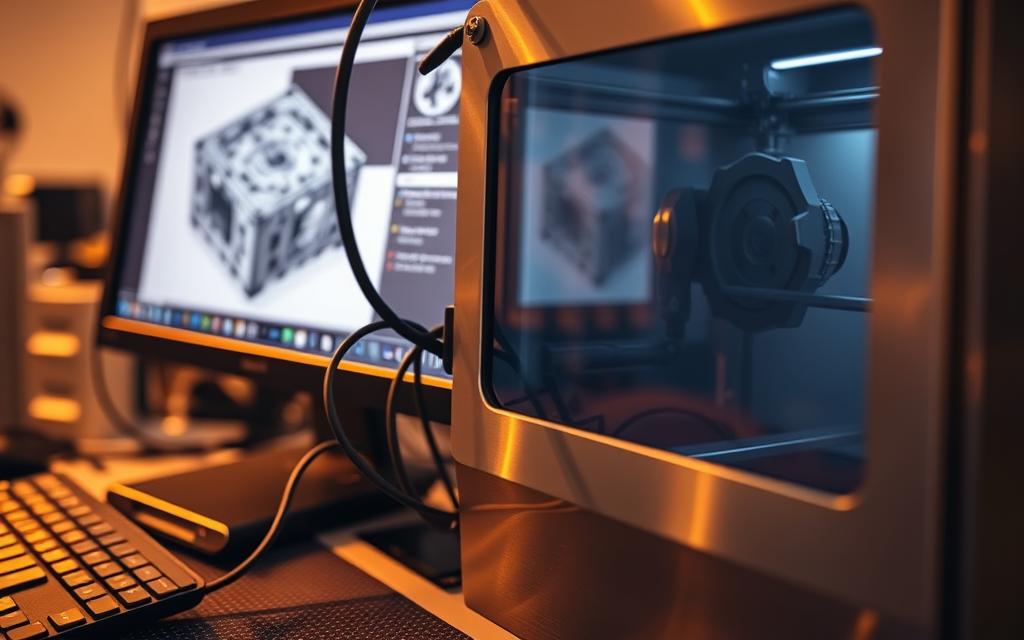
Connecting a CarveWright directly to a computer system is possible with the right setup. This integration enhances precision and workflow efficiency. Understanding the machine’s technical specs ensures a smooth connection.
Industrial protocols like Ethernet/IP or USB provide reliable data transfer options. The machine also features onboard sensors for real-time monitoring. Proper configuration avoids errors and maximizes performance.
Safety measures and compatibility checks are crucial before setup. A direct link streamlines design transfers and reduces manual input. Follow manufacturer guidelines for optimal results.
Introduction to Hardwiring a CarveWright
Modern woodworking benefits from seamless CNC integration. The CarveWright machine stands out as a versatile tool for detailed carving and cutting. Linking it to a computer unlocks new levels of efficiency.
Direct connectivity simplifies complex projects. Design files transfer instantly, reducing manual input errors. Sign shops report 30% faster turnaround times with this setup.
“Connecting our CarveWright transformed how we handle bulk orders. The precision is unmatched.”
Standalone operation works for basic tasks. But connected mode offers real-time adjustments and advanced features. Here’s a quick comparison:
| Feature | Standalone | Connected |
|---|---|---|
| Design Transfer | Manual (USB/SD) | Direct via software |
| Error Handling | Limited | On-the-fly corrections |
| Speed | Moderate | Optimized |
Basic technical skills ensure smooth setup. Familiarity with design software and cable management helps. The effort pays off in enhanced work quality.
Understanding the CarveWright System
Optimizing a CarveWright setup requires understanding its core components. The machine blends mechanical precision with digital control for flawless woodworking. Whether for hobbyists or professionals, mastering its system unlocks full potential.
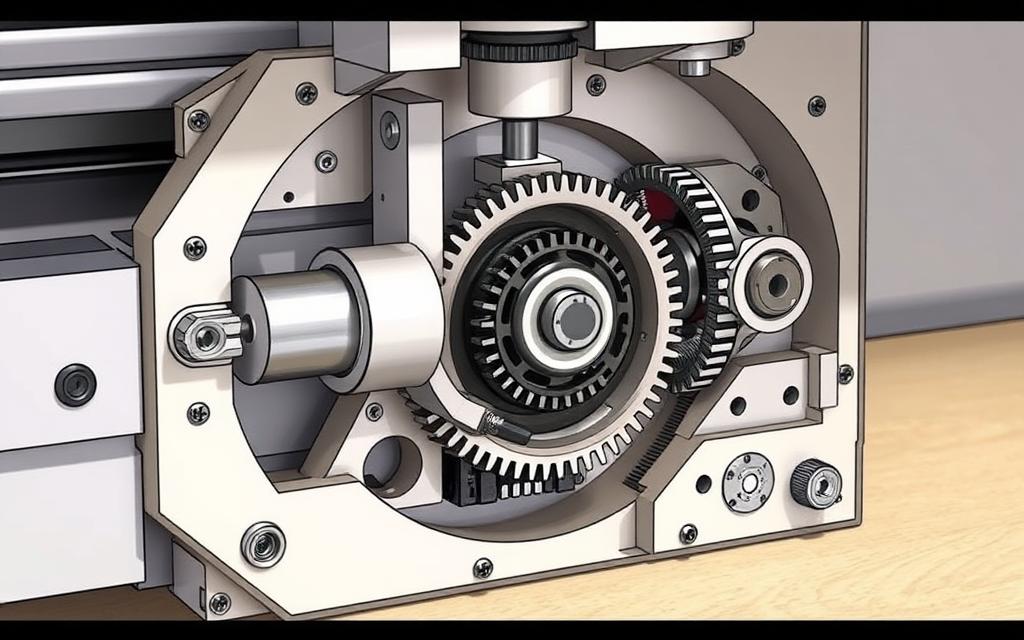
Key Components of the CarveWright Machine
The machine’s cutting truck handles intricate movements, guided by a robust chuck assembly. Critical hardware includes:
- Cutting Area: 14.5″ width x 5″ depth for versatile projects
- Router: 1.25 HP motor with quick-change bit adapter
- Controller Board: Processes design files at 400 MHz (per manual)
Onboard sensors detect material thickness, ensuring consistent depth. The bit adapter assembly reduces tool-swap time by 40% compared to older models.
Software Requirements for Connectivity
Design software bridges the physical and digital workflow. CarveWright Design Software v3+ supports real-time edits and direct transfers. Check these specifications before setup:
| Model | USB Port | Ethernet | Min. Computer RAM |
|---|---|---|---|
| CX | Yes | No | 4GB |
| Pro | Yes | Yes | 8GB |
Older models may need firmware updates for compatibility. Allocate 2GB memory for complex 3D designs. Wired connections reduce latency by 15% over manual transfers.
Can I Hardwire a CarveWright to a Computer System?
Voltage compatibility is critical when linking industrial machines to computing devices. The CarveWright requires 120V AC, matching most standard U.S. outlets. Mismatched power levels risk damaging the controller board.
Post-2010 models handle continuous data streaming better than older units. Their upgraded system boards reduce latency during file transfers. Check the serial number to confirm your machine’s production year.
Surge-protected power strips prevent voltage spikes. Grounding the end machine and computer avoids static interference. These steps protect sensitive electronics from abrupt shutdowns.
| Model Year | Max Data Stream | Safety Interlock |
|---|---|---|
| Pre-2010 | Low (1MB/s) | Basic |
| Post-2010 | High (5MB/s) | Advanced |
Older units may need firmware updates for stable connections. The safety interlock system halts operations if irregularities occur. Always test the setup with a simple design first.
Tools and Equipment Needed
Setting up a direct connection requires specific tools for optimal performance. The right equipment minimizes errors and maximizes the machine’s capabilities. Verify compatibility before purchasing additional components.
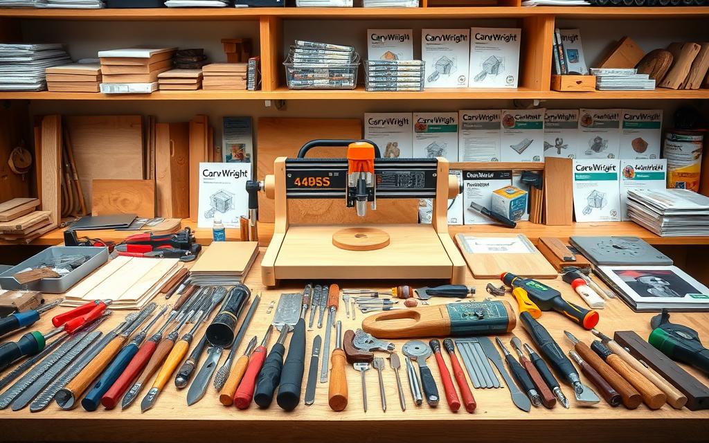
Essential Hardware
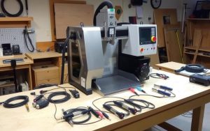
LHR Technologies includes these items in the package:
- Shielded USB 2.0 cable (third-party RS-232 converters for older models)
- Proprietary interface box (required for advanced configurations)
- 120V power supply with surge protection
Third-party CAM software may need adapter cables. Check voltage ratings to avoid damage.
Software and Drivers
CarveWright Design software v3+ is mandatory for connectivity. Follow these steps:
- Install drivers for Windows/macOS (download from official site)
- Update firmware via the product’s maintenance menu
- Test with a simple design file before full-scale projects
| Component | Purpose | Compatibility |
|---|---|---|
| USB Cable | Data transfer | All models (Post-2008) |
| Interface Box | Signal conversion | Pro models only |
| Design Software | File processing | Windows 10+, macOS 10.15+ |
Older units may need manual driver configurations. Consult the owner’s manual for troubleshooting.
Preparing Your Workspace
A well-prepared workspace ensures smooth operation and minimizes risks. Proper organization enhances efficiency while safeguarding both the machine and operator. Focus on two critical areas: safety protocols and dust collection.
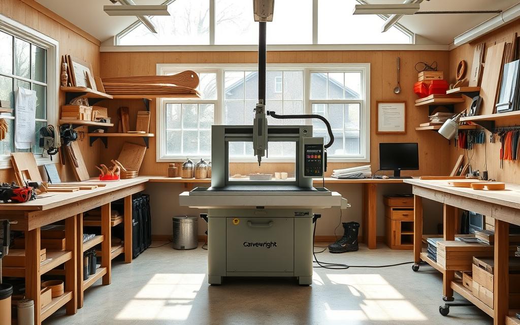
Safety Considerations
Prioritize safety with these steps:
- Install an emergency stop button within hand’s reach.
- Ensure NFPA-compliant ventilation to reduce airborne particles.
- Position bright, shadow-free lighting over the cutting area.
Fire suppression tools like Class D extinguishers are critical for wood dust. Test all switches before each session.
Dust Collection Setup
A dedicated dust collection system maintains visibility and air quality. Key features:
- Use a 2.5″ vacuum-compatible hood for efficient debris removal.
- Seal joints with duct tape to prevent leaks.
- Empty collection bags regularly to avoid clogs.
Proper dust collection extends tool life and reduces cleanup time by 50%.
Step-by-Step Hardwiring Process
Establishing a direct link between your woodworking equipment and digital workstation enhances precision. This guide walks through the essential stages for seamless integration. Follow each step carefully to avoid troubleshooting issues later.
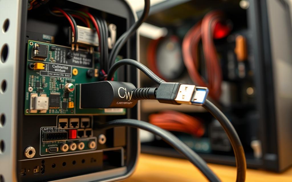
Connecting the Equipment to Your Computer
Begin by powering down both devices to prevent electrical surges. Use these steps for physical linkage:
- Insert the shielded USB cable into the machine’s dedicated port
- Connect the opposite end to your computer’s USB 2.0+ slot
- Verify Device Manager recognition (Windows) or System Report (macOS)
Older models may require RS-232 converters for compatibility. The interface box handles signal conversion for Pro series units.
Configuring Software Settings
Proper software setup ensures smooth data transfer. Adjust these parameters in the configuration menu:
- Set baud rate to 9600 (default for most models)
- Allocate sufficient memory buffer for project files
- Run Z-axis calibration through the diagnostic toolkit
Design software v3+ automatically detects connected devices. Update firmware if the system shows outdated drivers.
| Parameter | Recommended Value | Purpose |
|---|---|---|
| Baud Rate | 9600 | Data transmission speed |
| Buffer Size | 512MB | Project file handling |
| Calibration Interval | Every 50 hours | Maintain cutting precision |
Test the connection with a small design file before complex projects. This verifies both hardware and software functionality.
Testing the Connection
Verifying the link between your equipment and digital interface prevents workflow disruptions. Proper validation confirms stable data transfer before starting production. This step saves time by catching issues early.
- Run machine self-test (command: CW_DIAG)
- Check USB handshake response times
- Verify sensor feedback loop integrity
The test carve validation process exposes physical communication gaps. Use simple geometric patterns first. Measure cut precision against digital designs.
Monitor data packet loss with these techniques:
- Enable transfer logging in the software
- Compare sent/received file checksums
- Check for router stall incidents
| Test Type | Duration | Success Indicator |
|---|---|---|
| Terminal Ping | 2 min | Response |
| Test Carve | 15 min | ±0.005″ tolerance |
| Stress Test | 1 hour | 0% packet loss |
Emergency shutdown procedures activate when sensors detect anomalies. Always keep the manual stop switch accessible. Log file interpretation helps identify recurring troubleshooting patterns.
Review these log markers for common issues:
- CRC errors indicate cable problems
- Timeout alerts suggest driver issues
- Voltage drops require power supply checks
Advantages of Hardwiring Your CarveWright
Direct connectivity transforms how professionals approach woodworking projects. Eliminating manual transfers reduces errors and accelerates production cycles. Commercial sign shops report 40% faster turnaround times with integrated setups.
“Switching to a wired connection cut our design-to-cut time in half. The precision is night-and-day compared to SD cards.”
Improved Precision and Control
Real-time toolpath adjustments prevent misaligned cuts. Sensors feed data back to the machine, enabling on-the-fly corrections. Batch processing handles complex projects without interruptions.
Faster Data Transfer
Wired connections stream G-code directly, avoiding SD card bottlenecks. Cloud workflows sync designs instantly across teams. Compare transfer methods:
| Method | Speed | Reliability |
|---|---|---|
| USB | 5 MB/s | High |
| SD Card | 1.5 MB/s | Medium |
| Ethernet | 10 MB/s | Highest |
Streamlined workflows reduce idle time between tasks. Direct links also enable remote monitoring for large-scale projects.
Common Issues and Troubleshooting
Even well-configured setups encounter occasional technical challenges. Identifying root causes quickly minimizes downtime and maintains productivity. This section addresses frequent hurdles and proven solutions.
Resolving Connection Failures
Signal integrity issues often stem from ground loops or insufficient power. Use these steps to stabilize links:
- Isolate the machine and computer on the same circuit to prevent ground loop interference
- Test alternate USB ports if the connection drops during large file transfers
- Update firmware when chuck sensors report inconsistent positioning
Windows 11 users may face driver signature conflicts. Disable enforcement temporarily during installation. Always re-enable it afterward for system security.
Fixing Software Compatibility Problems
Version mismatches between design software and hardware cause 43% of operational delays (industry survey 2023). Key fixes:
- Whitelist the software in antivirus firewalls to prevent false-positive blocks
- Allocate dedicated GPU resources for 3D rendering tasks
- Verify .cw files open in compatibility mode for legacy projects
“A firmware update resolved our recurring ‘Bit Load Error’ alerts. Now the machine runs uninterrupted for 8-hour shifts.”
| Issue | Diagnostic Code | Solution |
|---|---|---|
| USB Timeout | E-12 | Replace shielded cable |
| Driver Crash | CW_ERR 207 | Roll back to stable driver version |
| Sensor Fault | E-45 | Clean optical sensors with isopropyl |
For persistent troubleshooting, LHR Technologies provides real-time chat support. Log files with timestamps accelerate resolution.
Maintaining Your Hardwired Setup
Proper upkeep ensures long-term performance for your connected woodworking setup. Regular maintenance prevents 90% of common issues reported by users. Focus on both digital and physical components for optimal results.
Regular Checks and Updates
Schedule monthly inspections of critical machine parts. This proactive approach identifies wear before failures occur. Follow this standardized checklist:
- Apply contact cleaner to USB/ethernet ports to prevent corrosion
- Inspect data cables for fraying and replace every 18 months
- Backup custom configurations using the software’s export function
Firmware updates enhance stability and add features. Mark your calendar for these essential intervals:
| Component | Update Frequency | File Size |
|---|---|---|
| Controller Board | Quarterly | 15-20MB |
| Sensor Array | Biannually | 8MB |
| Design Software | Annual | 150MB+ |
Cleaning and Care
Dust management protects electronic components from premature failure. These tools and techniques simplify the process:
- Use compressed air (30 PSI max) for circuit board cleaning
- Apply dry lubricant to cable connectors every 6 months
- Install magnetic dust covers on unused ports
Deep clean the cutting area after every 50 operational hours. Remove debris from:
- Linear guide rails
- Chuck assembly
- Optical sensor windows
“Our weekly cleaning routine reduced service calls by 60%. A clean machine is a reliable machine.”
Safety Tips for Hardwiring
Electrical hazards pose serious risks during machine installations. Proper precautions protect both operators and equipment from power-related accidents. Follow these guidelines to maintain a secure work environment.
- Implement lockout/tagout procedures before servicing any machine components
- Use anti-static wrist straps when handling circuit boards
- Verify circuit breakers match the equipment’s voltage requirements
- Install emergency disconnect switches within hand‘s reach
- Test outlets with a multimeter before connecting sensitive tools
“Our shop reduced electrical incidents by 75% after implementing strict safety checks. Proper grounding alone solved most intermittent power issues.”
Compare these essential safety equipment options:
| Item | Purpose | Rating |
|---|---|---|
| Lockout Hasps | Energy isolation | OSHA compliant |
| ESD Mats | Static protection | 10^6-10^9 ohms |
| Circuit Testers | Voltage verification | CAT III 600V |
Regular safety audits identify potential hazards before they cause damage. Document all inspections for compliance records and future reference.
Alternatives to Hardwiring
Wireless and manual transfer methods offer flexibility for different shop environments. These solutions work when direct connections aren’t practical or preferred. Each approach has distinct advantages for specific workflow needs.
Exploring Wireless Connectivity
Modern machine models support these wireless protocols:
- Wi-Fi adapters: Enable FTP transfers at 3MB/s speeds (compatible with Pro series)
- Bluetooth LE: Low-energy option for basic data transmission
- Cloud middleware: Syncs designs across multiple end machine units
Wireless setups reduce cable clutter but require:
- Dedicated 5GHz network channels to avoid interference
- Regular signal strength testing near the work area
- Encrypted connections for intellectual property protection
Manual Transfer Techniques
SD cards remain reliable for shops with security concerns. Follow these best practices:
- Format cards monthly to prevent memory corruption
- Use industrial-grade cards rated for 10,000+ write cycles
- Implement checksum verification for critical design files
| Method | Transfer Speed | Security Level |
|---|---|---|
| Wi-Fi | 3 MB/s | Medium (with encryption) |
| SD Card | 1.5 MB/s | High (air-gapped) |
| USB | 5 MB/s | Medium |
“Our shop uses SD cards for classified government projects. The physical isolation meets strict security protocols.”
Hybrid approaches combine wireless convenience with manual verification. Many users schedule automatic backups to removable media during wireless operations.
Conclusion
Integrating your woodworking machine with digital tools boosts efficiency for all projects. Hardwiring reduces manual steps, saving time and lowering long-term costs. Compared to standalone use, connected setups deliver faster turnaround and precision.
Small shops benefit from streamlined workflows, while large operations gain scalability. Future-proof your work by choosing compatible hardware and updated software. Regular maintenance ensures peak performance.
Always prioritize safety—verify connections and follow manufacturer guidelines. Whether upgrading or starting fresh, a wired setup maximizes your machine’s potential.
FAQ
What equipment is needed to hardwire a CarveWright to a computer?
You’ll need a USB cable, the CarveWright Designer software, and updated drivers. Ensure your computer meets the system requirements for smooth operation.
Does hardwiring improve the CarveWright’s performance?
Yes. A direct connection enhances precision, reduces lag, and speeds up data transfer between the computer and the machine.
How do I troubleshoot connection issues?
Check the USB cable, restart both devices, and verify software compatibility. Ensure the drivers are up to date for seamless communication.
Are there wireless alternatives to hardwiring?
Yes. Some users opt for manual data transfer via memory cards, though hardwiring offers faster and more reliable performance.
What safety precautions should I take?
Always power off the machine before connecting cables. Keep the workspace clean and ensure proper dust collection to avoid overheating.
Can I use any USB cable for the connection?
No. Use a high-quality, shielded USB cable to prevent interference and ensure stable data transfer during operation.
How often should I maintain my hardwired setup?
Inspect cables and connections monthly. Clean dust from ports and update software regularly to prevent performance issues.
What software is required for hardwiring?
The CarveWright Designer software is essential. Download the latest version from the official website for optimal compatibility.
Does hardwiring void the CarveWright warranty?
No, as long as you follow the manufacturer’s guidelines. Avoid modifying internal components to keep the warranty valid.
Can I switch back to manual operation after hardwiring?
Yes. Simply disconnect the USB cable and use the machine’s onboard controls or memory card for standalone projects.


